Creating Useful Wood Projects, Both Large and Small
Hammond Organ Cabinet Construction
Written by on January 12, 2017
BASE ASSEMBLY
Next, I made the connecting bottom 2 rails for each end. I used a mortising drill bit on the legs which was a bit tricky due to the shape of the leg. I cut the tenons on my table saw and tested for fit. It took a little adjustment, but they fit really nicely after a little creative chiseling. I glued them up with gorilla wood glue and used a scrap board as a spacer to keep them square. Keeping them square at this point was critical to insure a perfect fit under the main body holes. That glue holds like a blooming gorilla, and there ain’t no room for error:
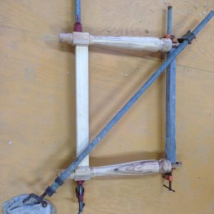
And here’s a picture of them glued up:
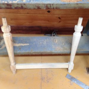
I wanted to build the legs with a left section and a right section, connected only by the rail at the bottom. They could be made with the top as a circular dowel, with holes in the upper body to accept the dowels. The original B3 cabinet used a rectangular section which goes through the bottom of the cabinet and attaches with glue and screws. Mine has to be removable, and so I decided to use a round dowel instead. I have worried all along that the cabinet may not be stable when I put the two together. I was worried about side to side racking. If that occurs, I’ll have to forget the whole portable idea, and salvage the case by gluing them in. I hope that DOES NOT HAPPEN!
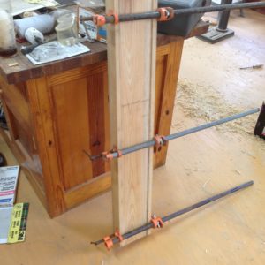
The cross member for the volume pedal and bass pedals (which we’re not using remember) would sit in slots on the leg rails and simply rest in position. I cut the stock, and glued it up using biscuits. I felt like Norm. (I can’t WAIT for some A – SIM – BAL – LEE, as he would always say.)
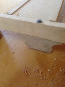
I next made the two decorative end pieces that bolt under the side leg rails. I made a pattern of the original, and cut them out. I glued them also. Here’s a closeup photo:
It was time to figure out some type of connection for the crossrail to join the side rails. I wanted to keep it simple, so I ended up using a piece of aluminum angle iron that would fit snugly into a wooden notch. Here’s a picture of what I came up with. The view is taken from what would be the inside under the main body looking out:

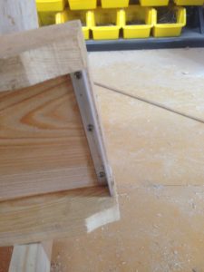
And here’s a photo of the underside of the center connecting piece showing the aluminum angle screwed on:
And finally, here’s the pieces set in place as they will eventually used:
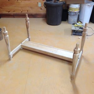
It looks like I’m beginning to get somewhere! I’ll let you know when we arrive.
0 Responses to Hammond Organ Cabinet Construction
Comments are closed.